ENCLOSURE SETUPDS
Orginal Wooden Enclosure
Date: 11-2001
I totally forgot I made this when I was making my setup! My first original box was made out of plywood holding the 3-Axis board, power supply, fuses, fan, and other misc. Items.
I totally forgot I made this when I was making my setup! My first original box was made out of plywood holding the 3-Axis board, power supply, fuses, fan, and other misc. Items.
METAL ENCLOSURE
Date: 4-21-01
I save up some money and designed my box. I had a sheet metal shop bend it using 1/8" aluminum. Overall they did an ok job (pic of box is after a lot of cleaning up). The price for the box $65. I used a Dremel with a router bit and the smaller router attachment to cut the box. Use the 35,000 rpm setting and get ready for a lot of mess!
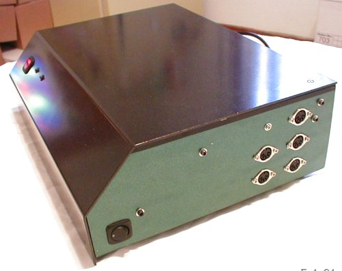
Here is my new enclosure! 3 days of work, 50+ hours, and it came out great! This side shows where my steppers plug into and the spindle over ride switch. I predrilled a hole for a sixth connection in case it was needed in the future. The box is painted with spray paints and holding up well.
Here is my new enclosure! 3 days of work, 50+ hours, and it came out great! This side shows where my steppers plug into and the spindle over ride switch. I predrilled a hole for a sixth connection in case it was needed in the future. The box is painted with spray paints and holding up well.
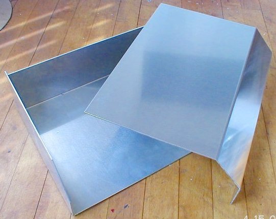
I designed my box and had a sheet metal shop bend it using 1/8" aluminum. Overall they did an ok job (pic of box is after a lot of cleaning up). The price for the box $65. I used a Dremel with a router bit and the smaller router attachment to cut the box. Use the 35,000 rpm setting and get ready for a lot of mess!

Here is my new enclosure! 3 days of work, 50+ hours, and it came out great! This side shows where my steppers plug into and the spindle over ride switch. I predrilled a hole for a sixth connection incase it was needed in the future. The box is painted with spray paints and holding up well.
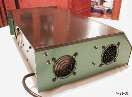
Here is the other side of the enclosure. These are the 2 exit holes for the fan. I have the fan blowing air into the box right at the heat sinks.
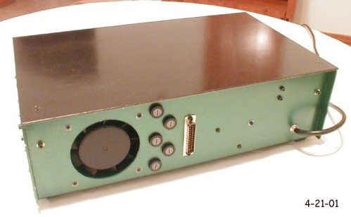
Here is the back. The fan, computer parallel port and fuses can be seen. It Works GREAT.
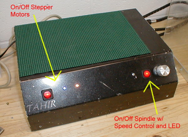
Currently, I have moved the spindle over-ride switch to the front and have added an AWO (all windings off) switch too.
Currently, I have moved the spindle over-ride switch to the front and have added an AWO (all windings off) switch too.
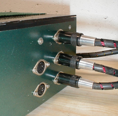
I wired the steppers using a radio shack 5 pin DIN connector. Using my lathe, I made a tapered backing out of 3/8" round aluminum stock so they would look nicer! I glued it to hold the plastic wire wrapping in place and it's done!
Enclosure Update
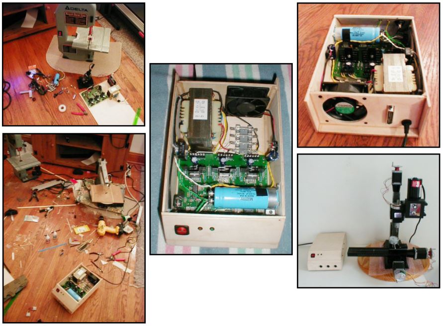
I have rewired my entire setup. Everything is now in the driver box, as I always wanted it. Here is a pic of the outside.
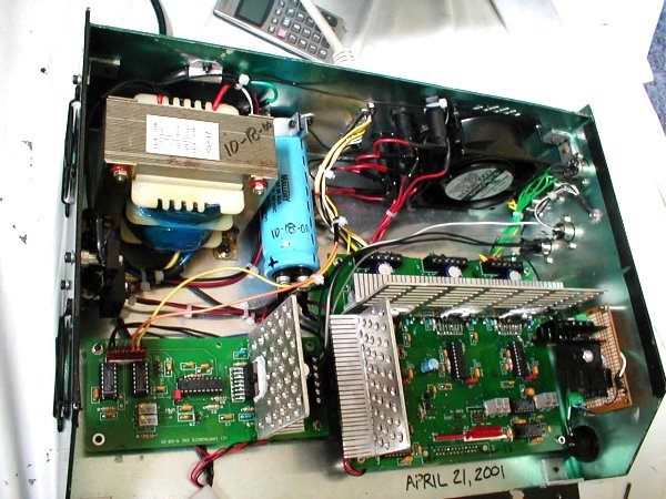
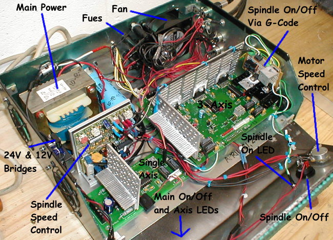
Here is everything inside! Clockwise:
- 4th axis board
- 25 amp/400 v bridge
- 10 amp 12-0-12 transformer
- 15,000 uF capacitor
- Fuses & radio shack 110v fan
- Motor outputs
- 3 axis board
- Board brother made for spindle on/off
- All standoffs for PC boards & power supply made out of aluminum and on the lathe
* Drivers Box Updated
Date: 01-2020
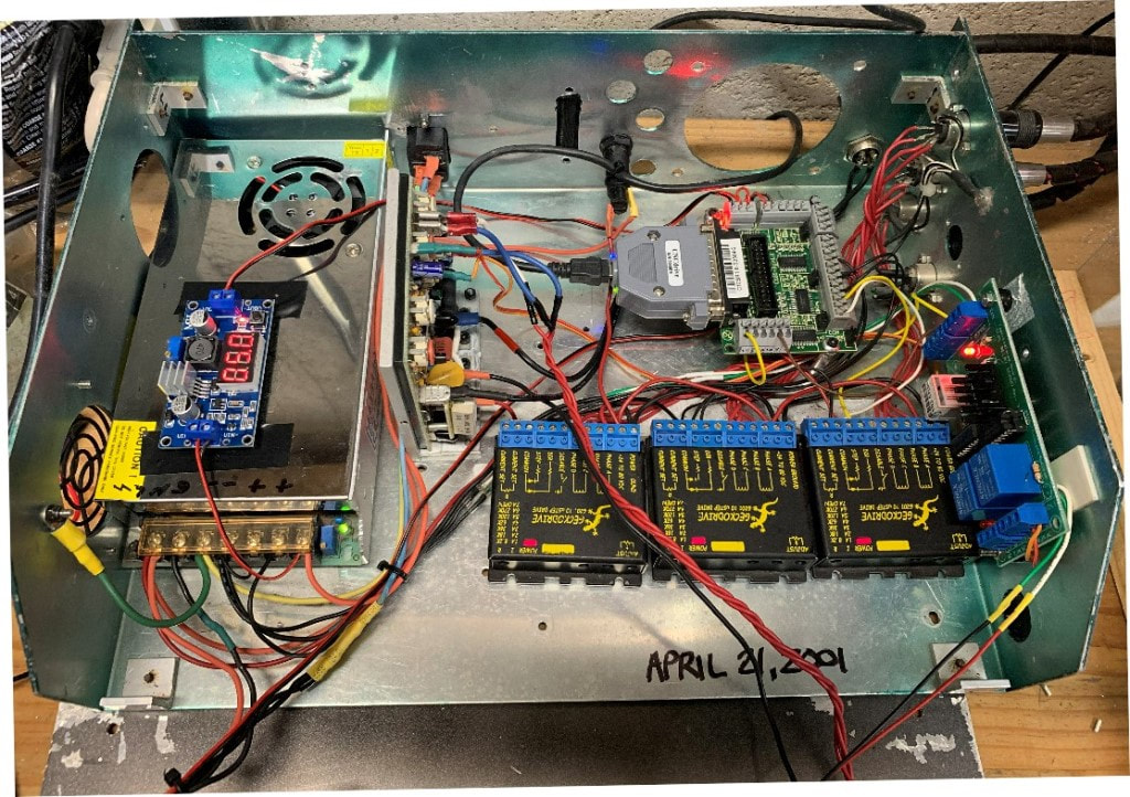
I have updated the enclosure for 2020! New boards, items and wiring. I have also removed individual fuses to each Gecko Drives to just one. I found if one fuse blows the other two drives still run which is cause either damage to the part or breakage of the endmill. Now if one stepper faults all 3 will stop.
I have updated the enclosure for 2020! New boards, items and wiring. I have also removed individual fuses to each Gecko Drives to just one. I found if one fuse blows the other two drives still run which is cause either damage to the part or breakage of the endmill. Now if one stepper faults all 3 will stop.
- Power Supply: 24V 10 Amps
- Stepdown: 5v Buck (click here)
- Sherline ESC in box
- UC100 Parallel to USB (click here)
- C10S Breakout Board (click here)
- Gecko Drives (click here)
- C15 Relay board for Spindle (click here)
- 1 Slow Blow 2amp fuse for all Geckos